


Car Light Delay OFF Timer Relay – Adjustable 1–360s with direct 12V out
See the best price here 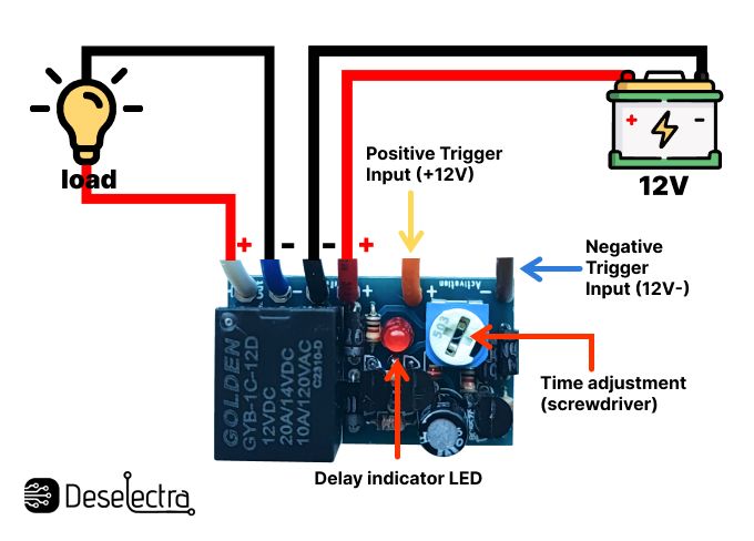
1. Product Overview
This module is a 12V DC adjustable Delay OFF timer relay designed for automotive lighting and general-purpose 12V automation systems.
The module activates a connected load immediately after receiving a trigger signal and continues supplying power to the output for a preset time before automatically switching OFF.
Unlike traditional dry-contact relay modules, this version provides a direct 12V output, making installation faster and easier for automotive lighting applications.
Typical Applications
- Delayed headlight shutdown
- Follow-me-home lighting systems
- Interior light delay
- Auxiliary automotive lighting
- LED strip control
- Car accessories with delayed shutdown
- Cooling fan delay control
- 12V automation systems
2. Technical Specifications
| Parameter | Specification |
|---|---|
| Operating Voltage | 12V DC |
| Adjustable Delay Time | 1–360 seconds |
| Output Type | Direct 12V Positive & Negative Output |
| Maximum Load Current | 20A |
| Trigger Input | Positive or Negative 12V Trigger |
| PCB Dimensions | 35 × 18 × 12 mm |
| Enclosure Dimensions | 40 × 17 × 21 mm |
| Wire Length | 10 cm |
3. Wire Identification
| Wire Color | Function |
|---|---|
| Red | +12V DC Supply Input |
| Black | Ground / GND |
| White | Delayed +12V Output |
| Blue | Output Negative / GND |
| Orange | Positive Trigger Input (+12V) |
| Brown | Negative Trigger Input (– Trigger) |
4. Wiring Instructions
Power Supply Connection
Red Wire
Connect to:
- Constant +12V battery supply
Important:
- Install a 20A fuse between battery positive and module input
Black Wire
Connect to:
- Vehicle ground / battery negative terminal
5. Output Connection
White Wire — Positive Output
Provides delayed +12V output to the connected load when the timer is active.
Connect to:
- Positive terminal of the lamp, LED strip, relay, or other 12V device
Blue Wire — Negative Output
Provides output ground connection.
Connect to:
- Negative terminal of the load
The module directly supplies power to the connected device, eliminating the need for additional relay wiring in many applications.
6. Trigger Input Connection
Positive Trigger Activation
Orange Wire
Connect to:
- +12V trigger signal
- Ignition switch
- ACC output
- Light switch
- Control switch
Operation
When +12V is applied:
- Timer activates immediately
- White wire outputs +12V
- Connected load powers ON
When trigger voltage is removed:
- Delay countdown begins
- Output remains active during countdown
- Output switches OFF automatically after preset delay
Negative Trigger Activation
Brown Wire
Connect to:
- Negative trigger signal
- Switched ground signal
Used in vehicles or systems where activation occurs through ground switching instead of positive voltage switching.
7. Operating Principle
- Module receives constant 12V power
- Module remains in standby mode
- Trigger signal activates timer
- White output wire provides +12V output
- Connected load powers ON
- Trigger signal is removed
- Delay timer starts counting
- Output remains active during countdown
- After preset time expires, output switches OFF automatically
8. Delay Time Adjustment
The module includes an onboard potentiometer for delay adjustment.
Adjustment Direction
- Clockwise rotation → decreases delay time
- Counterclockwise rotation → increases delay time
Adjustment Range
- Minimum: approximately 1 second
- Maximum: approximately 360 seconds
Fine adjustment allows precise timing customization for different automotive and automation applications.
9. Benefits
- Simple installation with direct 12V output
- No additional external relay required for most applications
- Supports both positive and negative trigger signals
- Wide adjustable delay range
- Compact size for hidden installations
- High current capability up to 20A
- Suitable for automotive and general 12V systems
- Reliable delayed shutdown operation
- Ideal for follow-me-home lighting systems
- Low standby power consumption
- Easy wiring with color-coded leads
10. Automotive Example Application
Delayed Headlight Shutdown
Example Connection
- Red wire → battery +12V through 20A fuse
- Black wire → vehicle ground
- Orange wire → ignition or headlight signal
- White wire → headlight positive input
- Blue wire → headlight ground
Operation
When ignition or headlights are turned ON:
- Module activates immediately
- Headlights receive power
When ignition or headlights are turned OFF:
- Timer countdown begins
- Headlights remain ON temporarily
- Power disconnects automatically after configured delay
Typical Use
- Follow-me-home lighting systems
- Delayed interior lighting
- Automatic accessory shutdown
11. Safety Information
- Use only with 12V DC systems
- Never exceed 20A load current
- Use external high-current relay for larger loads
- Verify wiring polarity before powering module
- Disconnect battery during installation
- Protect module from water and excessive heat
- Insulate all wiring connections properly
- Install appropriate fuse protection near power source